Thread Starter
#1
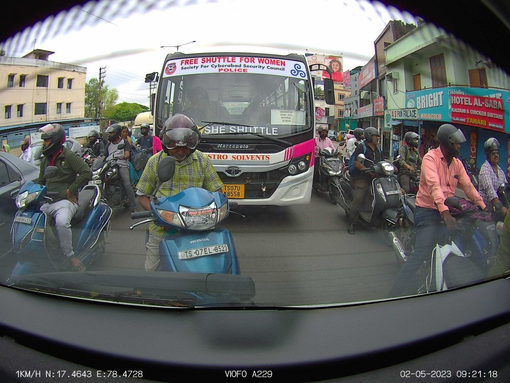
Having a dashcam is the need of the hour, majorly for safety reasons. My basic requirements were:
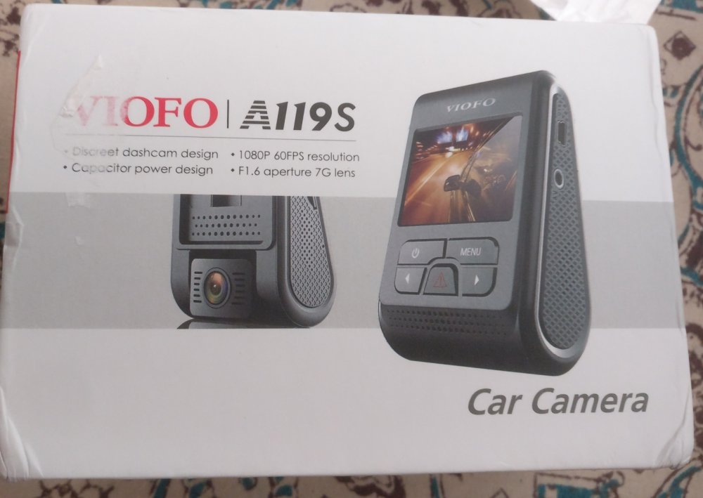
Viofo A119S
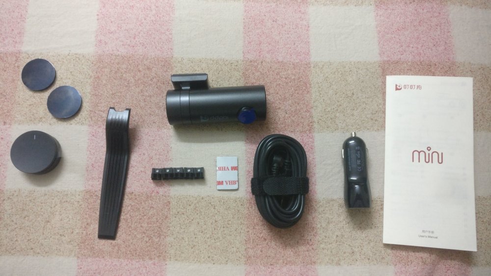
DDPai Mini
Overall be it the build quality, manufacturer support and user-friendly nature, I felt Viofo was the better option.
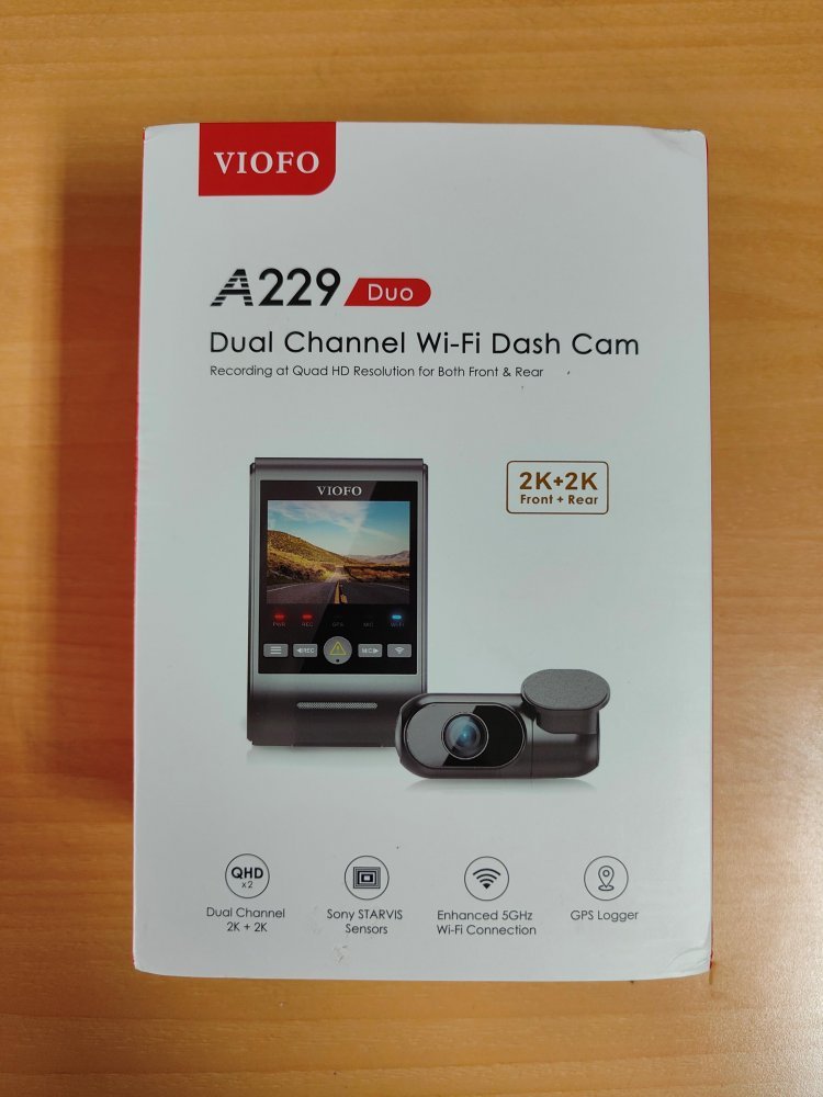
After a lot of reading and watching videos on YouTube about the A229 Duo and whether it is worth getting one, the overall consensus was it is a good quality camera with good footage from dual cameras. So here's what I've got:
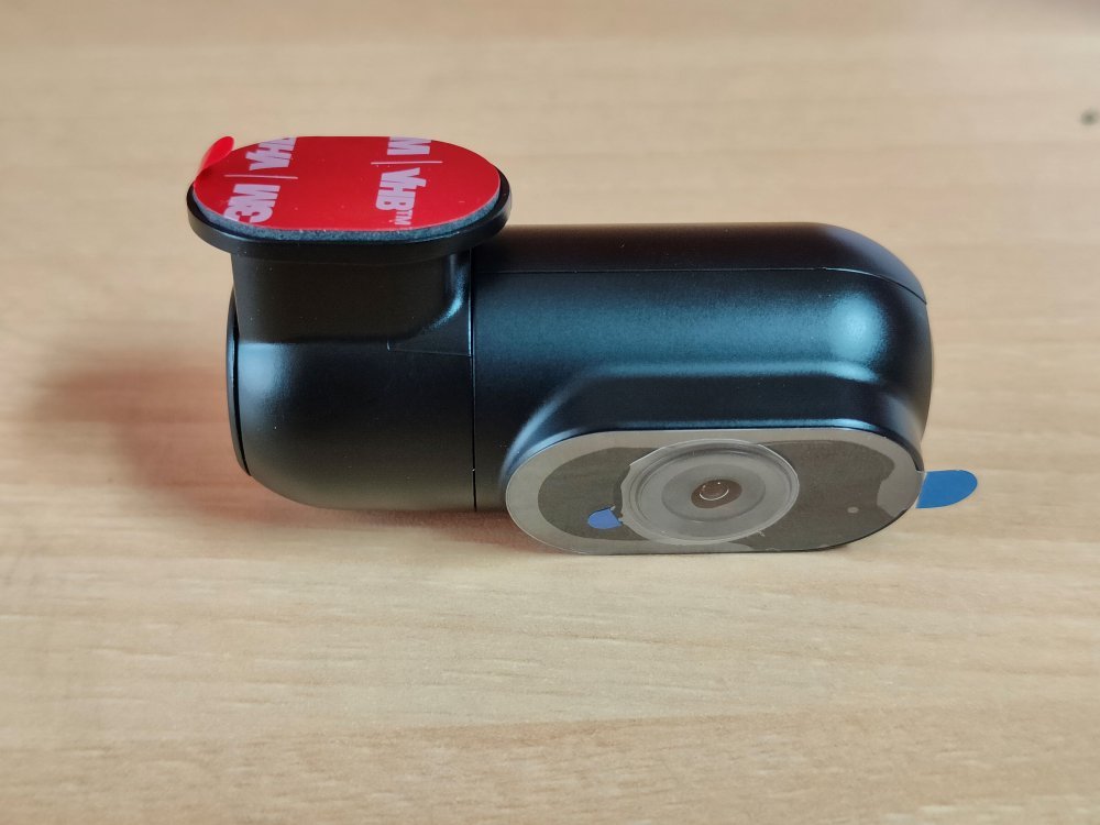
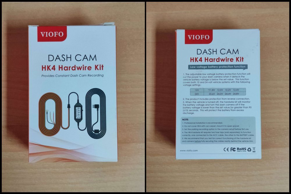
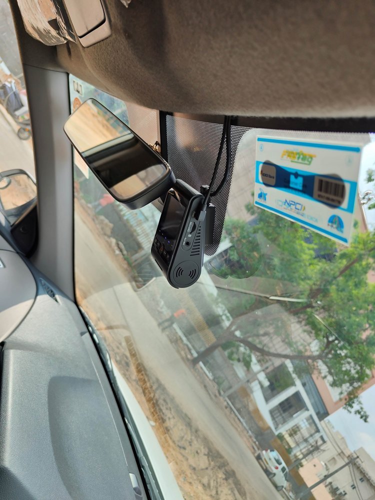
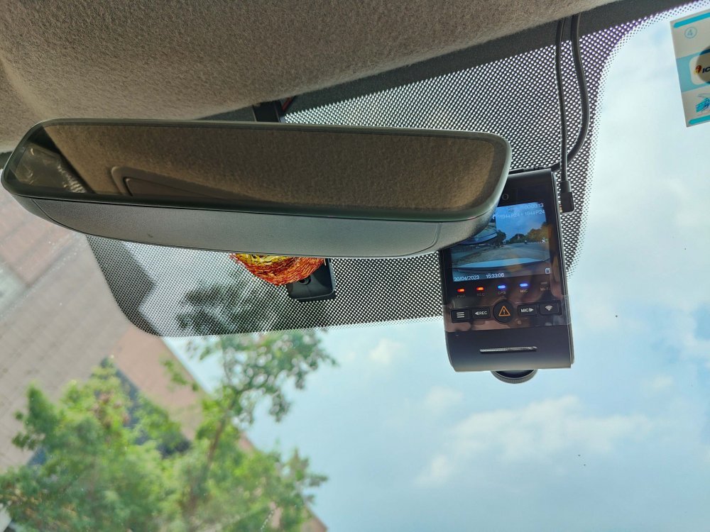
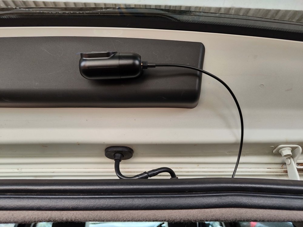
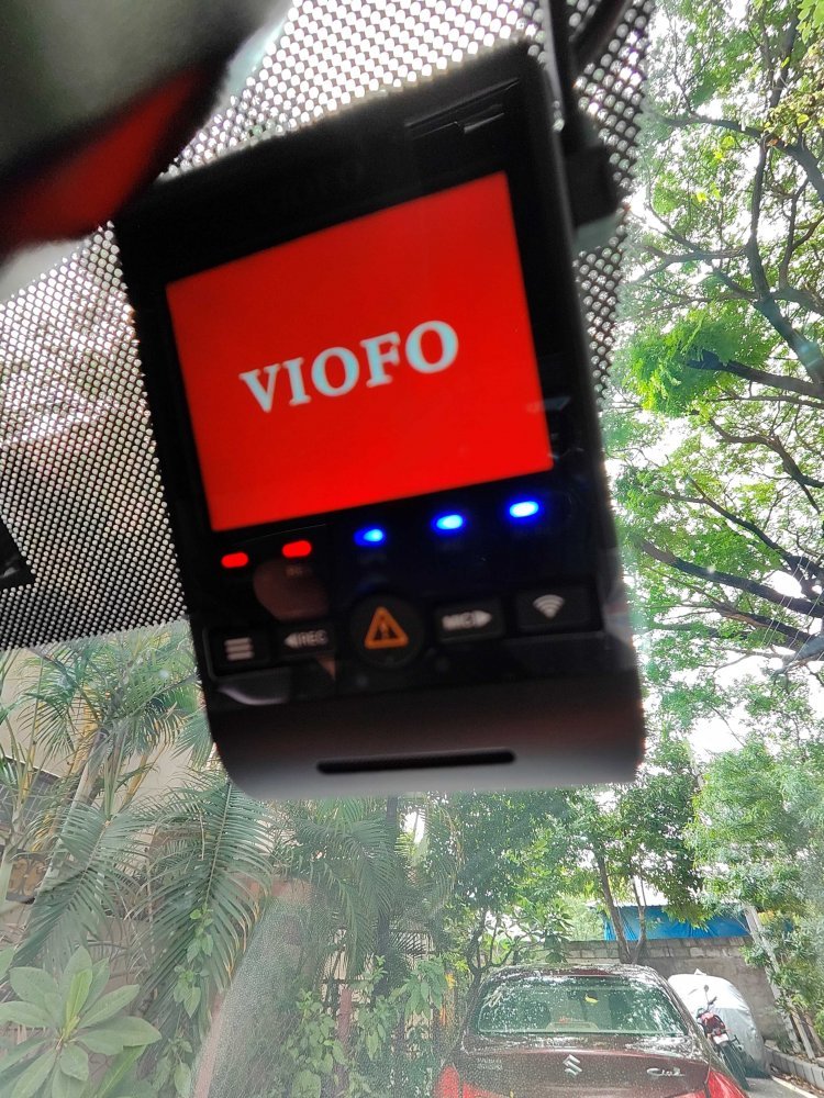
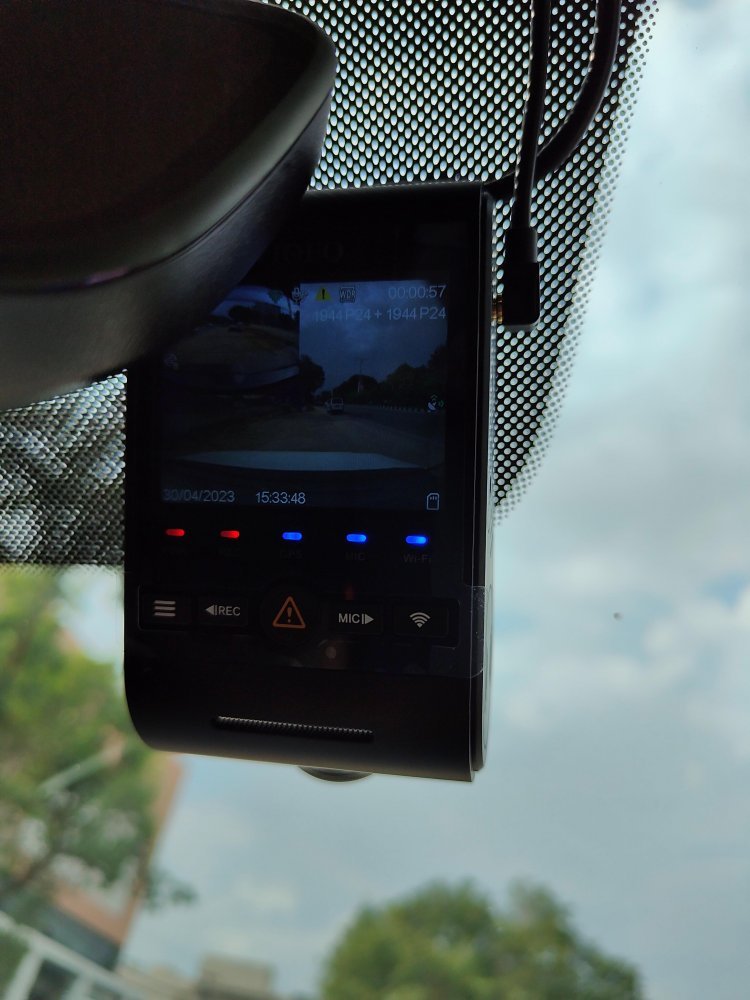
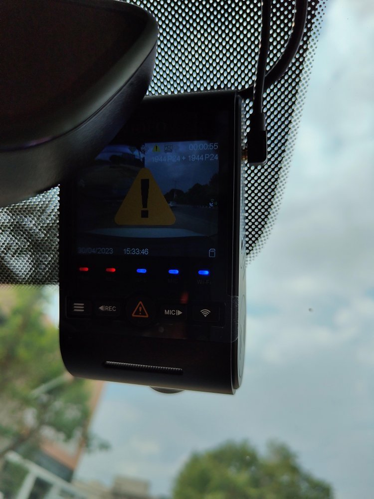
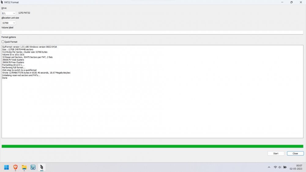
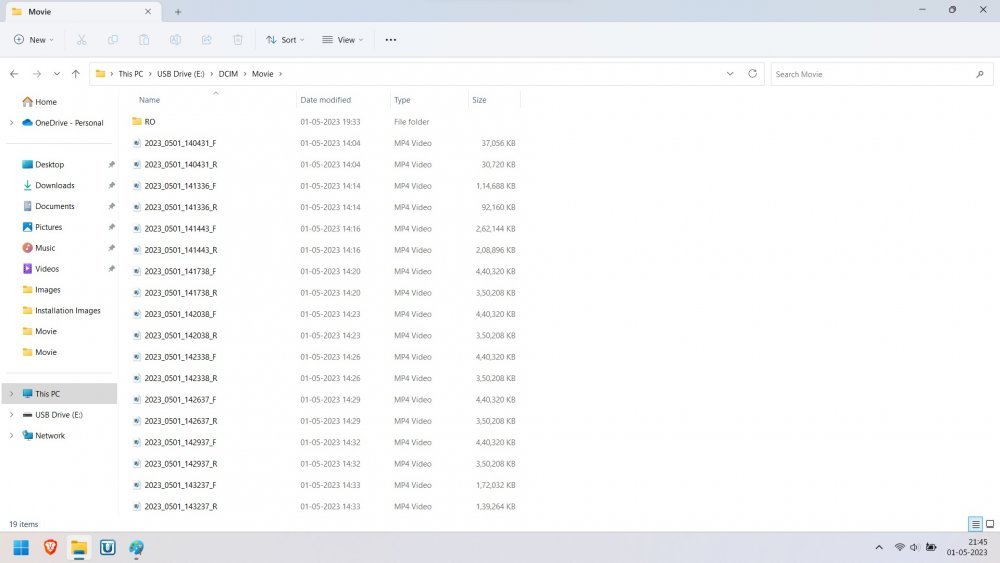
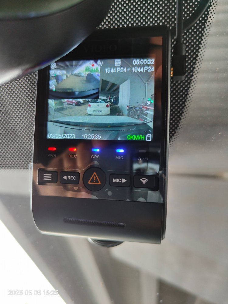
The Setup: Viofo A229 Duo + Viofo HK4 Hardwiring Kit + Viofo CPL Filter + SanDisk Extreme PRO (128GB) SD card.
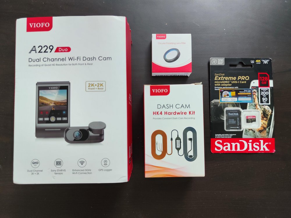
I purchased the Dashcam from the Indian distributor for Viofo dashcams i.e. Vijay Sales (Vadodara, GJ) through Amazon and CPL Filter + HK4 hardwiring kit from the Viofo India website. Both the earlier dashcams were purchased from AliExpress when it was serving Indian customers but now that Viofo has an Indian distributor, it was best to stick to them for the warranty-related issues and any guidance that could be required. And for the duration that I have spoken to them regarding the options etc, I was pretty happy with how they dealt with them and gave me options to choose from. They never tried to over-sell or push me for a costlier product during the discussion. Shipping through BlueDart was fast. Got the delivery the next day. (I have NO COMMERCIAL AFFILIATION, WHATSOEVER!).
- Dual channel
- At least 2K recording at the front. The rear can be 1080p
- Supports 256GB memory card size for longer recording.
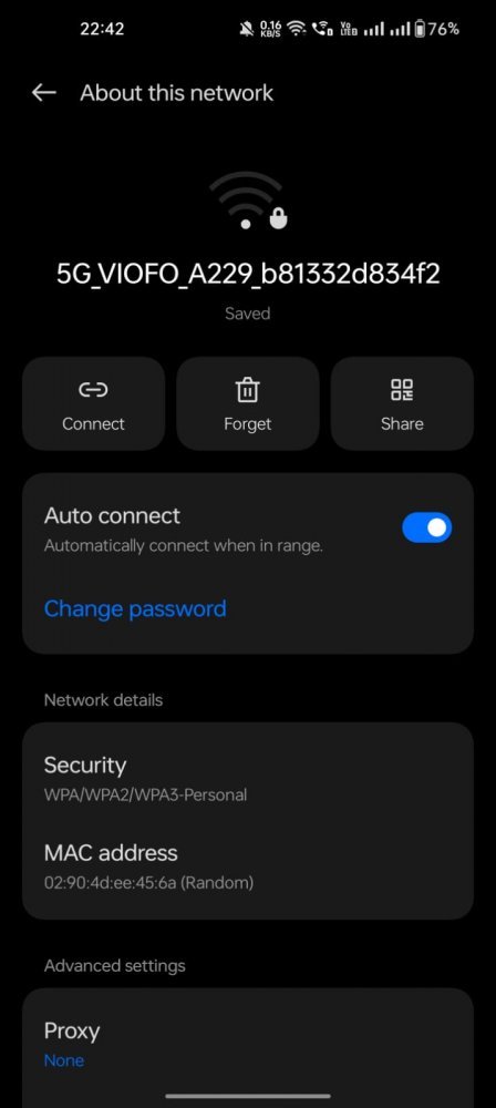
- Options with 5GHz WiFi.
- No battery inside the dashcam.
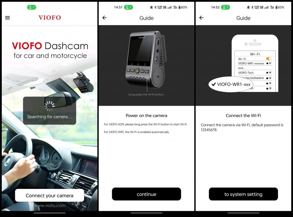
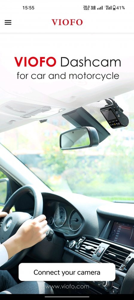
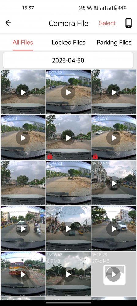
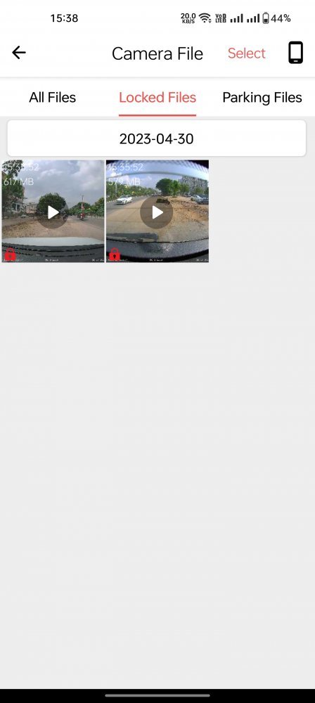
- User-friendly mobile application to pair the dashcam
- SafeCams Y3S Dual camera
- 70Mai A800S
- Viofo A129 Pro Duo 4K
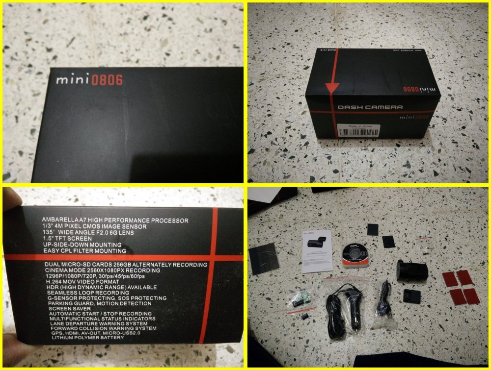
- Before this dashcam purchase, I used the following dashcams earlier i.e. the Mini 0806 (in my Swift) Viofo A119S and DDPai Mini (in my Creta).
Viofo A119S
DDPai Mini
Overall be it the build quality, manufacturer support and user-friendly nature, I felt Viofo was the better option.
After a lot of reading and watching videos on YouTube about the A229 Duo and whether it is worth getting one, the overall consensus was it is a good quality camera with good footage from dual cameras. So here's what I've got:
The Setup: Viofo A229 Duo + Viofo HK4 Hardwiring Kit + Viofo CPL Filter + SanDisk Extreme PRO (128GB) SD card.
I purchased the Dashcam from the Indian distributor for Viofo dashcams i.e. Vijay Sales (Vadodara, GJ) through Amazon and CPL Filter + HK4 hardwiring kit from the Viofo India website. Both the earlier dashcams were purchased from AliExpress when it was serving Indian customers but now that Viofo has an Indian distributor, it was best to stick to them for the warranty-related issues and any guidance that could be required. And for the duration that I have spoken to them regarding the options etc, I was pretty happy with how they dealt with them and gave me options to choose from. They never tried to over-sell or push me for a costlier product during the discussion. Shipping through BlueDart was fast. Got the delivery the next day. (I have NO COMMERCIAL AFFILIATION, WHATSOEVER!).
Last edited: